Friday 26 October 2012

Day 19 - Colours and Problems

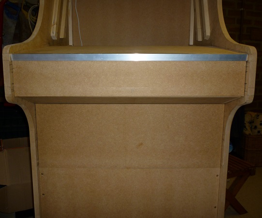
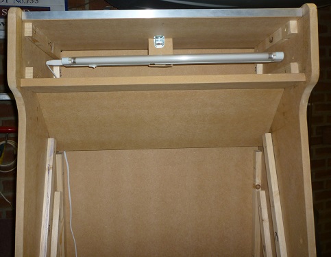
I finished priming everything, so that's two coats on every panel. Well, when I say finished I mean I'm not finished. For the visible parts (side panel, kick-board) I'm planning on a third coat, which should be done tonight. After which, I think the 1 litre paint will be completely used up.

After wet and dry sanding the second coat of the second side panel I hit a big problem (but just on the second side panel). The MDF was not smooth at all and had scratch lines and wood chips sticking out in small lumps all over the cabinet. But worse was you could see slight bumps in the MDF (no protrusion) where the screws had pushed out the MDF from the inside.

The odd thing is the screws are 35mm, the MDF is 18mm and the batons are 18mm. The screws are flush meaning they should be 1mm below the surface. My first though was I'd screwed it in too far but on the first cabinet there are no faults and the screws are the same. My second though was there was something up with the MDF (e.g. thinner and a failed QA). But I'm sure it wasn't like that.

On checking this morning it looks ok again (I think, I need to check again), so my thought now is the water in the wet and dry or the water in the primer/undercoat lifted the surface until it dried hence the stray MDF clumps and water penetration where the screws are.

Anyway, back to colours.

Originally back in the beginning the poll showed red was the preferred colour for the cabinet sides. Then after looking at colours I decided upon vermillion (a kind of orange with a red tint, i.e. not orange).

Reading a bike magazine I saw a review of the new Sukuki Gladius whose colour was described as 'retro' and a replica of the Barry Sheene bike of the 1970's. And I think it was just perfect.

When I say perfect, it's more like an 'international orange' than vermillion. Below is the original bike it was based on, which was slightly redder.

Anyway, you can see that as well as being nicely retro the colour scheme is very nice. My cabinet is already black (with chrome) so, depending on whether my artist friends has time to complete the art work and his direction I think vermillion, white, yellow and black is a very nice set of colours.


This could show best on the control panel, e.g. yellow or vermillion joystick tops, vermillion buttons with yellow surround and white player 1/2 coins.

Thin stripes around the outside edge of the sides would be very retro indeed :)

The conclusion to all of this was a mock-up of the cabinet using the colour scheme above and the space invader monster. Placement was done with the expert advice of snooker wizard Jamie from work and my cheese pasty loving mate Calla. The font is irrelevant. Click to zoom.


Finally, another one from Calla adding some depth to the scene with the monster stepping out of the cabinet. I think I like this one, but the font needs to change...


Tuesday 23 October 2012

Day 18 - It'll Be All White on the Night

The spec for the speakers was I wanted to be able to control the volume without going inside the cabinet or wiring up special things, the satellites small enough to fit in the speaker area and to have a sub-woofer with a bit of bass to be a little bit better than standard 2.0 PC speakers and to be able to easily make the speaker protrude from the kick-plate if necessary.

The speakers arrived (Logitech S220), very cheap ones but they really sound rather nice.  The satellites are about 18cm by 8cm. On the speaker grill I'll cut two holes 10cm by 4cm which cover the speaker grill that you can see then with the router recess from the inside leaving about 2mm. I can then mount the speakers so they are almost flush with the cabinet (showing only the speaker grill) without taking them apart.

The little dial you see is the volume (and headphone/mic), which I'll mount under the control panel on the sloping side so it's not that visible, but usable. All the cables seem long enough, though I may have to cut and extend the cable from the sub-woofer to the satellites. For the sub-woofer I haven't decided what to do but you can see the speaker is to the right (the hole on the front is the air in). I'll see how it sounds and in the worst case I'll cut a hole in the front kick-plate for the side speaker to fit through.

I primed the wood with the first two coats (leaving it overnight). While the MDF was smooth, it had an uneven texture so I sanded it down. First with 600grit then with 1200 grid - these are very fine but I figured the smoother I make the bare wood the better. Then they had a wipe clean to remove grease and dust and were ready for priming.

I used the MDF primer/undercoat I mentioned earlier (http://negnegneg.blogspot.co.uk/2012/10/day-11-almost-ready-for-priming-i.html) and from reading online the process was: using a foam gloss roller (even though it's water based) I loaded it with paint (but just enough to be covered) then the primer/undercoat was rolled on continuously until the paint ran out (i.e. not continuously reloading), finishing in light vertical strokes ensuring no visible overlaps.

Most of the panels took one go and the side panel and one of the back ones took a few re-loads after running dry. The other thing was to not go over the paint, i.e. literally put one coat on.

After a night drying (it's quick drying so probably only takes a few hours) the finish was quite rough and so I used wet and dry 240 grit (which is still quite smooth) and the result was quite smooth ready for the second coat.

If you look at the pictures (click to zoom) the side panel on the left has one coat, the other has two (it's because I had to fill a few holes so no painting until the filler had dried).  The second coat went on much quicker and used a load less paint. The edges (where the MDF had been cut) is also covered and there is no expansion or other problems you might get from cut wood.

The second coat looks very nice. When that's dry I'll move up to 600 grit and repeat. I've used about half the primer (it is a 1 litre tin, which should be enough for any cabinet) so the third coat I'll probably limit to the areas visible (side panel, kick-panel, speaker panel, bottom of the control panel) and that will get a 1200 grit sanding ready for painting.

I've found some oil (well solvent) based black which is matt and that will do the centre sections and I'll try my hand at rolling (in the same way as the primer). If it's not that good, I'll sand it down and spray it.


Friday 19 October 2012

Day 17 - A Letter From America

I had to stay in this morning and lucky I did as the t-molding and router bit arrived

I've started some videos. They're less exciting than watching paint dry I'm afraid.

Visit the channel for more videos
http://www.youtube.com/user/NeilNegNeilNeg

Here is video 5, cutting the slots for T-Molding


Thursday 18 October 2012

Day 16 - To Trackball or Not. That is the Question

There's only a handful of games using trackballs: http://en.wikipedia.org/wiki/List_of_trackball_arcade_games

Of which the main known ones will be Marble Madness, Centipede, Missile Command, various golf games. But marble madness is lovely :)


In the pictures (click to zoom) the left edge to the Player 1 joystick centre is about 8cm (3 inches) and the right edge of the Player 2 button is about 5cm (2 inches). Is this enough? (still waiting for somebody to comment....). Overall the width/height of the control panel is 66cm by 33cm (26inches by 13 inches).

In the picture only the circle of the trackball is visible, the rest is the housing underneath but obviously must not overlap controls.

I prefer trackball at the bottom (if I have one) but it means the controls are higher up and more chance of the wrist having to lie over the ball.

I think I may need to buy the controls, place them and then buy the trackball taking a hit on postage.

Monday 15 October 2012

Day 15 - Almost Ready for Priming

I finished the woodwork for the whole cabinet today. All that needs doing is a couple of holes for the speakers (the slanted piece below the marquee), a couple for the kick-plate for air to the pc and if I decide to put a sub-woofer in it, and a few random other holes for venting (e.g. behind the marquee light, rear vent for the pc).

The picture shows the chrome edging I'm using (instead of T-molding and marquee retainer clips) to surround the control panel (both edges) and marquee.

If you look at the piece of wood just below the control panel with the two horizontal chrome strips, I'm not 100% on whether I should get rid of the bottom one or not.

the problem is (from the picture anyway) it just looks too small. There's a picture below of the almost finished cabinet showing it without.


I also bought the primer for the MDF (it's from 'Tor' paints who supposedly make excellent speciality paints for covering damp (Zinnser brand, etc) and other surfaces. Tbh, the bloke in the factory shop said their standard acrylic primer would do the same job. But I figured it's the same price (£12 for 1 litre) and it's a primer and undercoat.


My T-Molding and router bit were shipped and picked up on Friday 11th and as of 12th had a status of  'Electronic Shipping Info Received' since then (15th). Hopefully it's just the US Postal Service is crap and it isn't lost.

In hind-sight I would change a couple of things with the cabinet:
1. Extrude the marquee by a couple of inches to allow more room for the speakers. the wood looks big enough but the way I've fitted it means it's a tight squeeze - the bottom wood for the marquee goes all the way to the edge rather than stopping where the speaker enclosure starts. This is to avoid the problem of light spillage from the light down through the  speakers.

2. I would shorten the height of the kick-plate (the bit where you stand where the coin-slot/drawer is) and increase the height of the control panel to give more space for a bit of art.

3. Move the drawer up (see below)

4. Possibly make the marquee taller by a centimetre or two.

At the back of the cabinet I fitted the door with a tiny chrome handle. It doesn't quite fit properly (probably just bad placement of the top hinge) so I'll be needing the expert help of Harry to sort that out - though nobody will ever see it.


For the control panel it didn't really fit to have a hinge so instead I opted to fit the wood below the control panel with dowels. So to access the control panel is a case of removing the drawer and pulling out the two wood panels giving loads of room to fit in. And if more space is required or the CP needs to be removed, it's fitted with angle brackets and will just pull straight out.

In doing so I realised I'd have two cuts showing (as from previous days I fitted a drawer in the middle of the kick-pate. So I removed the drawer front and replaced it with a larger one to go all the way to the top. If I were doing it from scratch I'd have simply made the drawer to fit directly below. The pictures below show the progress. Note the retaining bar I think I'll keep it as it's stopping the middle section from splaying out given there is nothing permanently screwed there.

I also added the wood for the speakers. It looks large but the space for speakers is tiny because the wood for the marquee goes all the way across to the back to stop any light from escaping so I'll only be able to fit maybe 3-4 inches in there. Below you can see the new drawer and the speaker.


Wednesday 10 October 2012

Day 14 - First Order

The tricky bits of wood surrounding the control panel need to be cut now (angles and stuff) and they will be dowelled in to allow access to the control panel.

Rather than have a hinge opening the control panel, you remove the drawer and the bits of wood above it upto the control panel all remove via dowels for loads of access space. The CP will be in place with some sort of simple wooden mechanism allowing it to be removed if necessary.

So I've cut the first piece (above the drawer) and it fits ok, after a bit of planing :)

Today I ordered the T-Molding and the slotted bit to cut the groove from GroovyGameGear.com. It needs a larger bit (0.08 inch - 2mm) rather than the normal 1/16th inch (1.5mm), and it's high-gloss black with chrome in-fill. Hope it doesn't look too bad. I suspect it was meant for going sideways round things not vertically.

The parts came to about $34 and the postage almost the same at $21. This is the most expensive T-Molding they sell (and it's not in the UK), but add the price of this router bit to the cheapest T-Molding you can buy in the UK and without postage it comes to more than what I paid in total. Isn't GB brilliant on over-charging for everything.

Sunday 7 October 2012

Day 13 - And Neg Said Let Their Be Light

Today I cut a few bits of wood to the required width (660mm), as every bit of wood from now on (I think) will be - there's only a few pieces to go really.

First I added a temporary strut to bring the sides in as because there is nothing holding the sides together at the front it splayed out naturally by about 2mm (you can see the strut in the picture with the angle bracket near to the control panel).

I then added the marquee wood and the 600mm strip light (14 watts). Short of a junction box and refusing to pay B&Q prices (the wholesaler is shut on the weekend) I called on my chief technical consultant Harry (pictured) who duly obliged and provided some technical expertise on stuff and was very impressed by my concealed drawer opening mechanism ;)

The speaker housing is not on yet and will be separate from the marquee to avoid any light bleed and the light is fully contained within the marquee (I'll probaby add some vent holes at the back.) Access to the speakers will be via the back where I'm going to cut a strip about 400mm down (behind the monitor) to allow full removal. This is the only bad thing on this design, just not enough room for speakers :(

Having done that, I temporarily added some MDF to trial the monitor and placement of control panel. The monitor rotates so I'm unsure as to mounting it on a strip of wood of fixing the stand down to allow manual rotation of the monitor. I know it's a bit small, but that's all I've got and it's hard to come by 4:3 monitors.


Saturday 6 October 2012

Day 12 - Tight Fitting Drawers

I think my wood jokes are wearing a bit thin now so I'm changing my headings and blogs to be completely serious from now on.

Today I created the drawer to house the keyboard/mouse. Essentially the wood for the drawer front was previously cut from the 660mm wood so the width/height are exact.

Now, you may be wondering what that erection coming out of the back of the drawers is, well the wood is about 8 inches long and slots through the hole you can see (the wife reckons it's more like 6 inches, but what do women know about measuring wood), and sticks out the back by about 3 inches.


The height is 130mm so I cut out three lengths of 90mm MDF to form the sides/back, one for the base and simply screwed/glued them together, then dowelled/glued the door. The reason for the 90mm height and not 130mm is because the batons joining the case together are showing so they form a natural stop for the drawer front, which you can probably see. The drawer is about three-quarters the depth of the cabinet, leaving a gap at the back for cables, etc.

The runners were simply the batons screwed to the side 90mm apart to fit the draw fit snugly. The idea is to not have to buy extra stuff and make everything out of the batons and MDF.

The reason behind the daft looking baton and ugly hole at the back of my cabinet is that I tinkered with grooves on the front for opening the drawer but the effect I really wanted was to be concealed. So what happens is that the cabinet will be against a wall and so to open the drawer you push the cabinet back slightly (it's on wheels) and the baton forces the draw open a little. The keyboard/mouse won't be used that much after it's all configured so it's a little pain for a better look.

Another reason is that it means the cabinet is a couple of inches from the wall, allowing the heat/air out (the fans will be at the back).

Wednesday 3 October 2012

Day 11 - Taking Shape

Today I put the side on the workbenches, attached the roller wheeled floor, squared it all up and knocked a few screws in.


Quite pleased with the result.

If I went back in time I'd change a few things like bring out the marquee further (to allow bigger speakers) and give it more depth (it's about 15cm for the marquee), make it deeper (it looks a bit wide and slim) to look better proportioned and allow a deeper monitor. But I'm still happy with the results.


Tuesday 2 October 2012

Day 10 - Having a Wheelie Good Time

With the single piece of 630mm wide MDF (2.4m tall) I already had cut from when I bought the timber I cut out the base of the cabinet, the top half of the back (the bottom will be a hinged cupboard), the kick-plate and the front drawer.

This was exactly 2.4m (well, minus 5mm for the cuts) as after measuring the base, drawer and kick-plate what was left I made for the back of the cabinet, so the cupboard at the back to access the computer will be about 50cm.

After that I made the base. Attaching the batons first so they'd be flush and making attaching to the cabinet easier. The wheels I bought about 6 years ago for £2.40.

I put the two spinning ones for the back.